Tuesday, November 6, 2012, 18:01 - LCR meter
How often do I debug electronic circuits and have a lot of SMD components lying on my table. To avoid mixing up wrong values I usually throw them away.Sometimes it would be handy to measure the values of SMD components.
Already quite some time ago I found a nice device for this purpose:
http://www.smarttweezers.com/
But... It is very expensive: about 400 US$
I thought: I can even build a single piece for 1/10th of the price.
The measuring principle is quite simple and well described in literature. Dave Jones also described it in one of his videos: http://www.youtube.com/watch?v=fs2MfTW4o_Q
The description starts at about 03:00.
A sinusodial signal is injected in the device under test and the amplitude and relative phase relation of voltage and current signals are measured to calculate the needed values.
Based on the Phase shift it is possible to detect the kind of device (inductor/resistor/capacitor) while the amplitude relations in conjunction with the frequency are used to calculate the component value.
Apart from only measuring the value and type of device it is also possible to measure for example the ESR of them.
The problem is: To be able to measure very small and very large values it is needed to have a very high dynamic range for current and voltage measurement.
After some calculactions I decided to use a programmable gain amplifier (PGA) to scale up the voltages before AD conversion.
I've choosen components to be able to operate at 3V CR2032 con cell:
- PGA113 as PGA. It has 2 input channels, so one channel can be used for voltage, the other one for current measurement
- Nokia 3210/3310 LC Display. It tested => It can run from a single CR2032 cell
- MSP430F5338: The 2 DAC outputs are used to generate a DC offset for the single supply system (virtual ground) and the sinusodial exitation signal. The internal ADC digitizes the signal, which is selected by the PGA.
- OPA378 operational amplifiers
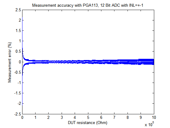
Measurement accuracy (!= resolution)
I made some simulations based on the accuracy of the MSP430 DACs and ADCs, and the PGA113. For simplicity I only did this analysis for resistive DUTs.

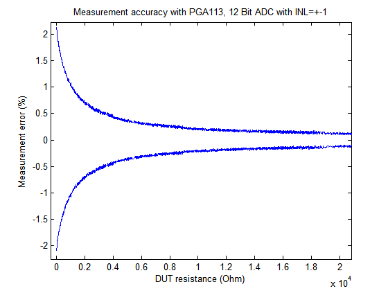
Closeup look for small values:

+-2% for small values is fair enough. The accuracy can be further improved by calibration. BTW: The simulated results are for non-calibrated systems!
The "small value accuracy" can be improved by choosing PGAs with higher gain.
Schematic
(click to zoom in):
For best accuracy I decided to make a few optimizations in the schematic:
- to avoid capacitive coupling termination resistors are inserted at some positions
- A "4 wire like" approach is used. For this reason an operational amplifier is placed very close to one of the measuring points.
Measurement principle
As the sinusodial signal is generated by the MCU and the MCU is also digitizing the voltage and current signals it they are totally synchronous to each other. For this reason it is possible to measure first the voltage signal and afterwards the current signal.
This saves an additional AD converter.
DAC0 will be set to VREF/2 (virtual ground)
DAC1 will output the sinusodial signal
The MCU will generate the signal by DMA transfers. A PWM-Timer will be setup to have the same period as the sinusodial signal.
The Timer will automatically trigger a single AD conversion per cycle. The duty cycle selects the position. The Duty cycle is changed a few times to digitize the signal at a different position once per sine-cycle.
This measurement principle allows high measurement signal frequencies while keeping the CPU load very low.
This will be done for the voltage and for the current signal.
Afterwards the phase of voltage and current signal has to be measured based on the acquired samples.
Phase and amplitude measurement
The resulting samples will be put in an FFT function which should generate a single peak bin. No FFT leakage will occur as DAC and ADC work synchronous to each other, so it is possible to use an FFT to measure the amplitude and the phase of the signal.
A very small FFT can be used to realize this functionality. Already a FFT of size 4 can be enough. Advantage: FFT of size 4 does not need any complex multiplications.
An FFT over traditional methods has a few other advantages: It acts also as small band filter, so noise in non-interesting frequency bins don't affect the measurement.
PCB
A few days ago my prototype PCBs arrived.
Aren't they beautyful? :-)
I also found a good way to realize the "tweezers". Measurement probes ("nails") are still missing, I will add some later.
For easier development I soldered the display with a long cable to the board. Later a very short cable can be used or the original clamping contacts of the display can be used.
Next steps:
- Get circuit up and running, try analog frontends, etc...
- Write "some" software :-)
1st update