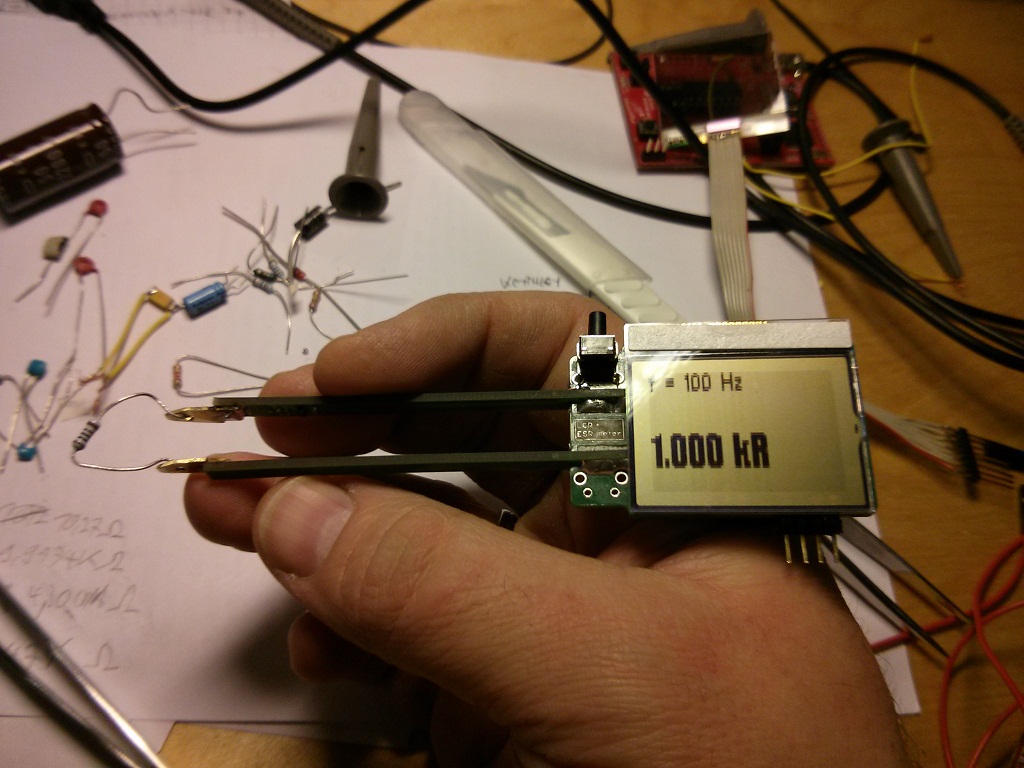
Thursday, December 27, 2012, 23:36 - LCR meter

I promissed to post a short status update of the project...
I'm already pretty satisfied with the current results. The measurements are reliable, repeatable and seem to have a good precision compared with my calibrated 6 digit multimeter.
For measurement frequencies of 100Hz and 1kHz I tried successfully components in the range of:
- Resistors: 0.3 Ohm - 5 MOhm
- Capacitors: 1.2 pF - 4700 uF
- Inductors: 10uH - 9 H
Current consumption
- about 8mA during measurement (including 2mA for the analog stuff)
- 20uA when it is turned off (can be improved by changing software, but is already acceptable)
The low current consumption allows the meter to be powered from a single 3V CR2032 battery.
Videos of the LCR meter
http://youtu.be/-Tj9n1g0hIk ...the meter in action
http://youtu.be/vTP0RzmvsDs ...the measurement signals shown on a scope
What I learned so far
dynamic current measurement / higher test frequencies
The current measurement over the 1K resistor using an opamp based subtractor was not a very good approach.
The problem is not the CMRR. Allthough it is not that good (abt. 60dB) I was able to compensate it digitally to over 100dB in my firmware. The main problem is the different delay in the 2 inputs which leads to problems because of the quantization steps of the DAC.
I will rewire it to a standard opamp based single supply I to V converter.
This change should also allow to allow much higher measurement frequencies (10kHz / 100kHz, maybe even 600kHz with some DSP tricks).
Crosstalk
2 termination resistors were put directly on the inputs of the PGA. This minimizes capacitive crosstalk of the current and voltage signal. This is not extremly important but increases the measurement range in case one of the signals is large and the other one is small (e.g. very small impedances or very large impedances).
MSP430 ADC reference
In first instance I used the internal 2.5V reference of the MSP430. This reference is not stable in my case, as ADC and DAC are running synchronous and the DAC has a very high conversion rate. I could see an oscillation of about +-20 digits in the ADC results.
I switched to use the analog supply voltage as reference. This will not decrease the precision, as DAC and ADC use the same reference.
Digital signal processing
The measurement of the phase and amplitudes is based on a DFT rather than an FFT. Only a single frequency bin has to be masured, so an DFT is in this case more efficient as a radix 2/4-FFT which would calculate all frequency bins.
The sine-tables which are output to the DAC are precalculated and are also used directly for the DFT calculation which saves memory.
Mechanical construction
The 2 PCB arms work well. They can be bended very easy and I don't have the feeling that they will break after a longer time of use.
But: It would be better to increase the length a little bit to be able to read the LCD from a better angle.
My current tweezer-tips are not very good but will be replaced later with better ones.